Direct lashing.
When it comes to direct lashing, we differentiate mainly between two types: inclined lashing and diagonal lashing. Diagonal lashing is by far the most commonly used method. This is why we focus here on this type of direct lashing.
Diagonal lashing.
Diagonal lashing is always preferable to tie-down lashing, since no special static pre-tensioning forces need to be applied. In contrast to tie-down lashing, the lashing equipment/lashing points are only subjected to light pre-tensioning. The lashing equipments are only subjected to higher loads if the forces occur as a result of strong braking, starting or intensive cornering.
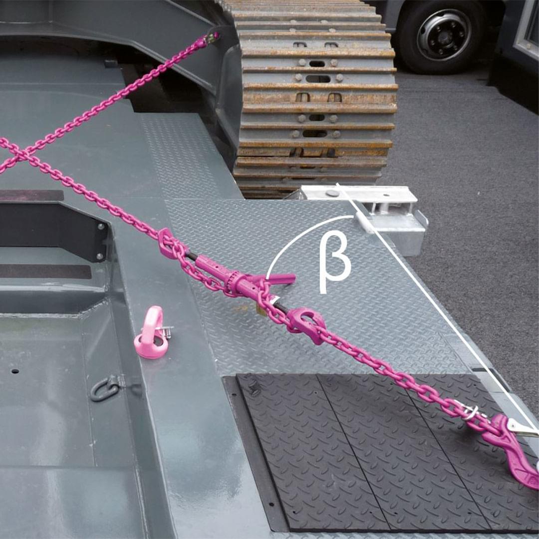
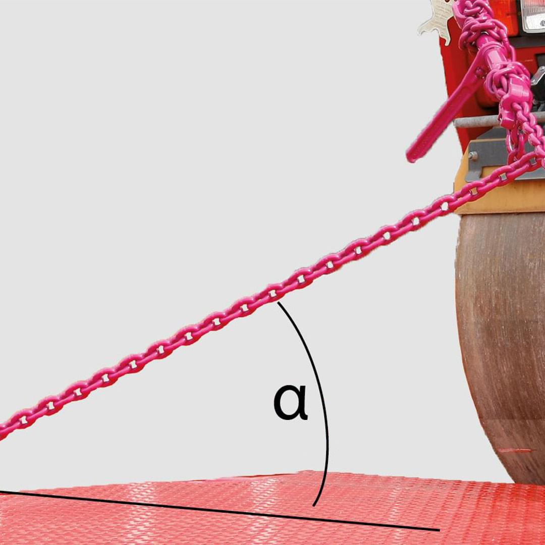
It is important that a number of characteristics are taken into account for diagonal lashing. This concerns the arrangement and positioning of the lashing lines in relation to the respective loading directions. Two angle plans (horizontal and vertical) must be taken into account for diagonal lashing and thus two angles must be defined. The two figures are intended to facilitate a clear definition of the angles to be taken into account.

Horizontal angle β

Vertical angle α
The angles α and β play a decisive role in the calculation. The angle β is the horizontal angle between an imaginary straight line from the lashing point towards the driver’s cab and the chain strand. The vertical angle α is the angle between the loading area and the chain strand. RUD chains offer an easy to use calculation aid with an angle meter, which makes the determination of angles α and β child’s play.
Using this calculation aid, you can very quickly and safely select the correct lashing chain. If β becomes very small, there will be a very high load on the lashing equipment when cornering. If β becomes very large, there will be a very high load during braking/acceleration. In the ideal case β should be between 20° and 45°.
In extreme cases (if angle β = 90°), an indefinitely high force would theoretically occur in the lashing equipment. This should illustrate that extreme crosswise lashing as securing in the direction of travel, which can often be seen on construction vehicles or rollers, is the most unfavourable type of load securing in the direction of travel.
With an angle α, the optimal lashing force result is given, between 0° and 30°. As the angle α increases, so does the load on the lashing equipment, which theoretically increases to infinity with an angle of 90°.
Calculation example:
Mass (m) = 18,000 kg ≈ 18,000 daN = G
Vertical angle of the lashing strands: α = 10°
Horizontal angle of the lashing strands: β = 40°
Number of the effective lashing chains in each direction:
Friction coefficient µ, dirty/icy wood loading area: µ = 0
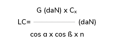
The friction coefficient µ of the excavator on the dirty wooden loading area is insignificant and not taken into account in the first calculation. The formula for the necessary lashing equipment with the permissible lashing force (LC = lashing capacity) is:

cos 10° = 0,984
cos 40° = 0.766
cx acceleration factor in direction of travel = 0.8; against direction of travel = 0.5

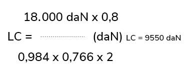
For the excavator with a weight of 18,000 kg ≈ 18,000 daN and the lashing arrangement shown, a lashing equipment must be selected that has at least the permissible lashing force of 9,550 daN.
This would be a RUD ICE lashing chain with a nominal size of 10 mm.